Irene Christy
15512057
- Prof. Ir. Ricky Lukman Tawekal, MSE, PhD/ Eko Charnius Ilman, ST, MT - KL 4200 Pipa Bawah Laut - Program Studi Teknik Kelautan - Institut Teknologi Bandung - http://www.ocean.itb.ac.id
Piping Elbows and Bends are very important pipe fitting which are used very frequently for changing direction in piping system. Piping Elbow and Piping bend are not the same, even though sometimes these two terms are interchangeably used.
A BEND is simply a generic term in piping for an “offset” – a change in direction of the piping. It signifies that there is a “bend” i.e, a change in direction of the piping (usually for some specific reason) – but it lacks specific, engineering definition as to direction and degree. Bends are usually made by using a bending machine (hot bending and cold bending) on site and suited for a specific need. Use of bends are economic as it reduces number of expensive fittings.
Bend.
An ELBOW, on the other hand, is a specific, standard, engineered bend pre-fabricated as a spool piece (based on ASME B 16.9) and designed to either be screwed, flanged, or welded to the piping it is associated with. An elbow can be 45 degree or 90 degree. There can also be custom-designed elbows, although most are catagorized as either “short radius” or long radius”.
Elbow.
The difference between them is as follows:
Bend is a generic term for any offset or change of direction in the piping. It is a vague term that also includes elbows.
An elbow is an engineering term and they are classified as 90 deg or 45 deg, short or long radius.
Elbows have industrial standards and have limitations to size, bend radius and angle. The angles are usually 45 deg or 90 degrees. All others offsets are classified as pipe bends.
Bends are generally made or fabricated as per the need of the piping; however elbows are pre fabricated and standard, and are available off the shelf.
Bends are never sharp corners but elbows are. Pipe bending techniques have constraint as to how much material thinning can be allowed to safely contain the pressure of the fluid to be contained. As elbows are pre fabricated, cast or butt welded, they can be sharp like right angles and return elbows which are 180 degrees.
Elbow is a standard fitting but bends are custom fabricated.
In bends as the pipe is bent and there is no welding involved, there is less pipe friction and flow is smoother. In elbows, the welding can create some friction.
All elbows are bends but all bends are not elbows.
Bend has a larger radius then elbows.
Generally the most basic difference is the radius of curvature. Elbows generally have radius of curvature between one to twice the diameter of the pipe. Bends have a radius of curvature more than twice the diameter.
Whenever the term elbow is used, it must also carry the qualifiers of type (45 or 90 degree) and radius (short or long) – besides the nominal size.
Elbows can change direction to any angle as per requirement. An elbow angle can be defined as the angle by which the flow direction deviates from its original flowing direction (See Fig.1 below).Even though An elbow angle can be anything greater than 0 but less or equal to 90°But still a change in direction greater than 90° at a single point is not desirable. Normally, a 45° and a 90° elbow combinedly used while making piping layouts for such situations.
Elbows or bends are available in various radii for a smooth change in direction which are expressed in terms of pipe nominal size expressed in inches. Elbows or bends are available in three radii,
Long radius elbows (Radius = 1.5D): used most frequently where there is a need to keep the frictional fluid pressure loss down to a minimum, there is ample space and volume to allow for a wider turn and generate less pressure drop.
Long radius elbows (Radius > 1.5D): Used sometimes for specific applications for transporting high viscous fluids likes slurry, low polymer etc. For radius more than 1.5D pipe bends are usually used and these can be made to any radius.However, 3D & 5D pipe bends are most commonly used
Short radius elbows (Radius = 1.0D): to be used only in locations where space does not permit use of long radies elbow and there is a need to reduce the cost of elbows. In jacketed piping the short radius elbow is used for the core pipe.
Here D is nominal pipe size in inches.
There are three major parameters which dictates the radius selection for elbow:
Space availability,
Cost, and
Pressure drop.
Pipe bends are preferred where pressure drop is of a major consideration.
Use of short radius elbows should be avoided as far as possible due to abrupt change in direction causing high pressure drop.
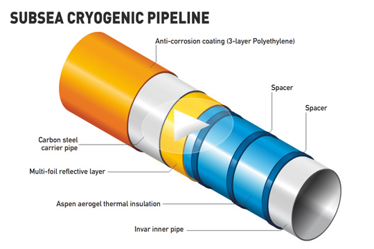
Pipeline thermal insulation is a prevention due to temperature difference between pipeline outer surface and inner part of the pipeline. Pipeline thermal insulation is considered as important since its contribution to corrosion as well as wax and hydrate problems in offshore pipeline system.
Pipeline insulation as figured below:
1. Condensation That Lead to Corrosion
Pipes operating at relatively low temperature (with hot fluid flows inside, e.g. offshore pipeline) increases the potential for existing water vapour to condense on pipe surface. And this moisture may lead to corrosion on the pipeline surface.
2. Wax and Hydrate Formation
In oil and gas industry, excessive cooling of the product during transportation can result in drop out of high molecular weight waxes and asphalt. This happens due to the working temperature of the pipeline (deep in the depth, above the seabed where the temperature is relatively low). In wet gas systems, hydrate formation can block pipelines (flow).
INSULATION METHODS
There are few methods that can be used for insulation, such as use of cooling spool, material selection, and pipe in pipe (PIP).
Use of Cooling Spools
There can be significant cost benefit from cooling the product stream from very high temperature wells to minimize the thermal expansion forces and then maintaining this lower temperature for through efficient pipeline insulation reducing the volume of post lay rock dump or trenching required or enabling more conventional materials and analysis techniques to be employed.
Material Selection
Typically, pipeline insulation must be able to withstand the stresses imposed as a result of the installation methods and strong enough to withstand constant external pressure and function effectively when submerged and saturated.
The dry, load-free environment within the annulus of the pipe allows non-typical insulation materials with much lower thermal conductivity to be applied subsea than has historically been possible e.g. rock-wool systems etc. There are also few materials used for insulation have been around for a few decades and include polypropylene, polyurethanes, epoxies and rubbers.
Figure below shows installation of material for pipeline insulation:
PIPE IN PIPE (PIP)
Pipe in Pipe (PIP) is installation of a second pipeline around the product pipeline from the seawater surrounding it and creates a dry chamber around the pipeline that can be engineered to accommodate a range of advanced insulation techniques.
Figure above illustrates Pipe in Pipe technology for offshore pipeline.
Midline Tie-in or Above Water Tie-in (AWTI) is an operation where two laid down pipelines on the seabed are welded together after being lifted above water using vessel davits.
For AWTI we determine/provide:
Steps for recovering the pipelines
Welded Configuration for recovered pipes
Steps for lowering the completed pipeline
Weld excavation analysis
Minimum weld thickness assessment for removal of the welding clamp
Offshore Procedures to be followed during execution
Static Code checks (pipeline integrity) are performed for every static loadcase. Dynamic Analysis is performed for the respective worst case in Pipe Recovery, Welded configuration and Laydown. DNV buckle checks are used to ascertain pipe integrity during dynamics.
Corrosion can be defined as the destruction or deterioration of a material because of reaction with its environment. Corrosion is a natural occurance and inevitable. Especially in seawater environment, corrosion is a threat for carbon steel pipe (offshore pipeline). Corrosion will damage pipeline and leads to pipe leak in which will be dangerous for the circumstances surround. Petroleum industry spends a million dollars per day to protect its pipelines. And so, there is urgency to protect and prevent pipeline from corrosion.
There are several methods that can be used to prevent and decrease the rate of corrosion on offshore pipeline. These methods are:
MATERIAL SELECTION
This method is just simply selecting the best and appropriate alloy carbon steel to a particular environment. For instance, the use of nickel-based alloy steel allows pipeline to withstand seawater environment without putting additional sacrificial anodes or impressed current, yet it’s far more expensive than having ordinary carbon steel with cathodic protected.
USE OF INHIBITOR
Sometimes corrosion in offshore pipeline attacked from inside (compounds brought by the fluid inside pipe e.g. sulphate). This can be helped by adding inhibitor. Inhibitor is a substance that when added in small concentrations to an environment, decreases the corrosion rate, such as chromate and nitrate.
CATHODIC PROTECTION
Cathodic protection is achieved by supplying electrons to the metal structure to be protected. Basically, cathodic protection has the pipeline become cathode, instead of anode, that way it won’t be corroded. There are two ways to cathodically protect a stucture. Firstly, Impressed Current Cathodic Protection (ICCP) and Sacrificial Anode Cathodic Protection (SACP).
1. Impressed Current Cathodic Protection (ICCP)
ICCP supplies electron by flowing electrical current from a power supply. This method is suitable for large structures regarding cost.
For pipelines, anodes are arranged in groundbeds either distributed or in a deep vertical holes depending on several design and field condition factors including current distribution requirements.
2. Sacrificial Anode Cathodic Protection (SACP)
This method is also known as Galvanic Coupling. In the usual application, a galvanic anode, a piece of a more electrochemically “active” metal, is attached to the vulnerable metal surface where it is exposed to the corrosive liquid. Galvanic anodes are designed and selected to have a more “active” voltage (more negative electrochemical potential) than the metal of the target structure.
COATING
Relatively thin coatings of metallic and inorganic materials can provide a satisfactory barrier between metal and its environment. The chief function of such coatings is to provide an effective barrier.
Coating can be in the form of, for example, cladding. Cladding involves a surface layer of sheet metal put on by rolling two sheets of metal together. For instance, a nickel and a steel sheet are hot-rolled together to produce a composite sheet with, say, 1/8 inch of nickel and 1 inch of steel. This way the steel are protected with its environment since nickel is layered on the surface. Moreover, in the application for offshore pipeline, high density polyethylene(HDPE) and polypropylene layer can be coated on pipe bare surface. Both HDPE and polypropylene coating have low water permeation which will improve isolation of the pipe from seawater surrounds. Coating for pipeline is illustrated as below:
source :
Fontana, Mars G. Corrosion Engineering. Singapore. 1987.
Conduits to transfer materials from the seafloor to production and drilling facilities atop the water's surface, as well as from the facility to the seafloor, subsea risers are a type of pipeline developed for this type of vertical transportation. Whether serving as production or import/export vehicles, risers are the connection between the subsea field developments and production and drilling facilities.
Similar to pipelines or flowlines, risers transport produced hydrocarbons, as well as production materials, such as injection fluids, control fluids and gas lift. Usually insulated to withstand seafloor temperatures, risers can be either rigid or flexible.
Types Of Risers
There are a number of types of risers, including attached risers, pull tube risers, steel catenary risers, top-tensioned risers, riser towers and flexible riser configurations, as well as drilling risers.
The first type of riser to be developed,attached risersare deployed on fixed platforms, compliant towers and concrete gravity structures. Attached risers are clamped to the side of the fixed facilities, connecting the seabed to the production facility above. Usually fabricated in sections, the riser section closest to the seafloor is joined with a flowline or export pipeline, and clamped to the side of the facility. The next sections rise up the side of the facility, until the top riser section is joined with the processing equipment atop the facility.
Also used on fixed structures,pull tube risersare pipelines or flowlines that are threaded up the center of the facility. For pull tube risers, a pull tube with a diameter wider than the riser is preinstalled on the facility. Then, a wire rope is attached to a pipeline or flowline on the seafloor. The line is then pulled through the pull tube to the topsides, bringing the pipe along with it.
Building on the catenary equation that has helped to create bridges across the world,steel catenary risersuse this curve theory, as well. Used to connect the seafloor to production facilities above, as well as connect two floating production platforms, steel catenary risers are common on TLPs, FPSOs and spars, as well as fixed structures, compliant towers and gravity structures. While this curved riser can withstand some motion, excessive movement can cause problems.
Used on TLPs and spars,top-tensioned risersare a completely vertical riser system that terminates directly below the facility. Although moored, these floating facilities are able to move laterally with the wind and waves. Because the rigid risers are also fixed to the seafloor, vertical displacement occurs between the top of the riser and its connection point on the facility. There are two solutions for this issue. A motion compensator can be included in the top-tensioning riser system that keeps constant tension on the riser by expanding and contracting with the movements of the facility. Also, buoyancy cans, can be deployed around the outside of the riser to keep it afloat. Then the top of the rigid vertical top-tensioned riser is connected to the facility by flexible pipe, which is better able to accommodate the movements of the facility.
First used offshore Angola at Total's Girassol project,riser towerswere built to lift the risers the considerable height to reach the FPSO on the water's surface. Ideal for ultra-deepwater environments, this riser design incorporates a steel column tower that reaches almost to the surface of the water, and this tower is topped with a massive buoyancy tank. The risers are located inside the tower, spanning the distance from the seafloor to the top of the tower and the buoyancy tanks. The buoyancy of the tanks keeps the risers tensioned in place. Flexible risers are then connected to the vertical risers and ultimately to the facility above.
A hybrid that can accommodate a number of different situations,flexible riserscan withstand both vertical and horizontal movement, making them ideal for use with floating facilities. This flexible pipe was originally used to connect production equipment aboard a floating facility to production and export risers, but now it is found as a primary riser solution as well. There are a number of configurations for flexible risers, including the steep S and lazy S that utilize anchored buoyancy modules, as well as the steep wave and lazy wave that incorporates buoyancy modules.
While production and import/export risers transfer hydrocarbons and production materials during the production phase of development;drilling riserstransfer mud to the surface during drilling activities. Connected to the subsea BOP stack at the bottom and the rig at the top, drilling risers temporarily connect the wellbore to the surface to ensure drilling fluids to not leak into the water.
Pipe in Pipe (PIP) is installation of a second pipeline around the product pipeline from the seawater surrounding it and creates a dry chamber around the pipeline that can be engineered to accommodate a range of advanced insulation techniques.
Figure above illustrates Pipe in Pipe technology for offshore pipeline.
Pipe-in-Pipe Offshore Construction
1. Fixed
suitable for majority of lay vessels
field joint uses bulkheads or swaged connectors, no movement between flowline and carrier pipe
permits vacuum in annulus
heat loss from flowline to carrier pipe through metal connectors
2. Sliding
S-lay & J-lay
uses a butt weld on carrier pipe and allows the flowline to move freely
flowline may or may not have alignment spacers
thermal insulation may be on the outside if flow-through-annulus active heating is used
3. Restrained
polymer bulkheads to hold insulation material in place
these bulkheads transfer the load during installation and provide concentric alignment
Subsea flowlines are used for the transportation of crude oil and gas from subsea wells, manifolds, off-shore process facilities, loading buoys, S2B (subsea to beach), as well as re-injection of water and gas into the reservoir. Achieving successful tie-in and connection of subsea flowlines is a vital part of a subsea field development.
Subsea fields are developed using a variety of tie-in solutions. Over the past decade, FMC Technologies has developed a complete range of horizontal and vertical tie-in systems and associated connection tools used for the tie-in of flowlines, umbilicals and jumper spools sizes 2” - 36” and for single and multibore application. FMC’s horizontal and vertical tie-in systems have been extensively installed in many of the deepest, highest pressure and largest diameter subsea applications around the world.
Vertical Tie-in System
Vertical connections are installed directly onto the receiving hub in one operation during tie-in. Since the Vertical Connection System does not require a pull-in capability, it simplifies the tool functions, provides a time efficient tie-in operation and reduce the length of Rigid Spools.
Stroking and connection is carried out by the the Connector itself, or by the ROV operated Connector Actuation Tool (CAT) System.
Horizontal Tie-in System
Horizontal Tie-in may be used for both firstend and second-end tie-in of both flowlines, umbilicals and Jumper spools. The termination head is hauled in to the Tie-in point by use of a subsea winch. Horizontal Tie-in may be made up by Clamp Connectors operated from a Tie-in tool, by integrated hydraulic connectors operated through the ROV, or by non-hydraulic collet connectors with assistance from a Connector Actuation Tool (CAT) and ROV. Horizontal connections leave the flowline/umbilical in a straight line, and is easy to protect if overtrawling from fishermen should occur.
A gooseneck (or goose neck) is a 180° pipe fitting at the top of a verticalpipethat prevents entry of water. Common implementations of goosenecks are ventilator piping or ducting for bathroom and kitchen exhaust fans, ship holds, landfill methane vent pipes, or any other piping implementation exposed to the weather where water ingress would be undesired. It is so named because the word comes from the similarity of the pipe fitting to the bend in a goose’s neck.
Gooseneck may also refer to a style of kitchen or bathroom faucet with a long vertical pipe terminating in a 180° bend.
To avoid hydrocarbon accumulation, a thermosiphon should be installed at the low point of the gooseneck.
Hydrostatic testing has long been used to determine and verify pipeline integrity. Several types of information can be obtained through this verification process.
However, it is essential to identify the limits of the test process and obtainable results. There are several types of flaws that can be detected by hydrostatic testing, such as:
Existing flaws in the material,
Stress Corrosion Cracking (SCC) and actual mechanical properties of the pipe,
Active corrosion cells, and
Localized hard spots that may cause failure in the presence of hydrogen.
There are some other flaws that cannot be detected by hydrostatic testing. For example, the sub-critical material flaws cannot be detected by hydro testing, but the test has profound impact on the post test behavior of these flaws.
Given that the test will play a significant role in the nondestructive evaluation of pipeline, it is important to determine the correct test pressure and then utilize that test pressure judiciously, to get the desired results.
When a pipeline is designed to operate at a certain maximum operating pressure (MOP), it must be tested to ensure that it is structurally sound and can withstand the internal pressure before being put into service. Generally, gas pipelines are hydrotested by filling the test section of pipe with water and pumping the pressure up to a value that is higher than maximum allowable operating pressure (MAOP) and holding the pressure for a period of four to eight hours.
ASME B 31.8 specifies the test pressure factors for pipelines operating at hoop stress of ≥ 30% of SMYS. This code also limits the maximum hoop stress permitted during tests for various class locations if the test medium is air or gas. There are different factors associated with different pipeline class and division locations. For example, the hydrotest pressure for a class 3 or 4 location is 1.4 times the MOP. The magnitude of test pressure for class 1 division 1 gas pipeline transportation is usually limited to 125% of the design pressure, if the design pressure is known. The allowed stress in the pipe material is limited to 72% of SMYS. In some cases it is extended to 80% of SMYS. The position of Pipeline and Hazardous Material Safety Administration (PHMSA) is similar. Thus, a pipeline designed to operate continuously at 1,000 psig will be hydrostatically tested to a minimum pressure of 1,250 psig.
Based on the above information, let us consider API 5L X70 pipeline of 32-inch NPS, that has a 0.500-inch wall thickness. Using a temperature de-rating factor of 1.00, we calculate the MOP of this pipeline from following:
P= {2x t x SMYS x1x factor (class1) x 1} / D (ASME B 31.8 Section, 841.11)
Substituting the values:
P= 2x 0.5 x 70,000 x1 x0.72 x1/32 = 1,575 psig
For the same pipeline, if designed to a factor of 0.8, the MOP will be computed to be 1750 psig.
If the fittings were the limiting factors of the test pressure, then the following situation would arise.
If the fittings used in the system are of ANSI 600 then the maximum test pressure will be (1.25 x 1,440) 1,800 psig. This test pressure will support the requirements of both factor 0.72 and 0.8.
If, however, ANSI 900 fittings were chosen for the same pipeline system, the test pressure (1.25 x 2,220) 2,775 psig would test the pipeline but would not test the fittings to their full potential.
Let us first discuss the design factor of 0.72 (class1). In this case the test would result in the hoop reaching to 72% of the SMYS of the pipe material. Testing at 125% of MOP will result in the stress in the pipe reaching a value of 1.25 x 0.72 = 0.90 or 90% of SMYS. Thus, by hydrotesting the pipe at 1.25 times the operating pressure, we are stressing the pipe material to 90% of its yield strength that is 50,400 psi (factor 0.72).
However, if we use a design factor of 0.8 - as is now often used - testing at 125% of MOP will result in the stress in the pipe to 1.25 x 0.8 =1. The stress would reach 100% of the yield strength (SMYS). So, at the test pressure of 1800 psig the stress will be 56,000 psi (for factor 0.8). This will be acceptable in case of class 600 fittings. But, if class 900 fittings were taken into account, the maximum test pressure would be (1.25 x 2,220) 2,775 psig and the resulting stress would be 88,800 psi which will be very near the maximum yield stress (90,000 psi) of API 5L X 70 PSL-2 material.
Test Pressure And Materials SMYS
Though codes and regulatory directives are specific about setting test pressure to below 72% or in some cases up to 80% of the SMYS of the material, there is a strong argument on testing a constructed pipeline to “above 100% of SMYS,” and as high as 120% of SMYS is also mentioned. Such views are often driven by the desire to reduce the number of hydrotest sections, which translates in reduction in cost of construction. In this context, it is often noted that there is some confusion even among experienced engineers on the use of term SMYS and MOP/MAOP in reference to the hydrotest pressure.
It may be pointed out that the stress in material (test pressure) is limited by the SMYS. This is the law of physics, and is not to be broken for monetary gains at the peril of pipeline failure either immediate or in the future.
In this regard, section 32 of directive No. 66 of the Alberta Energy and Utilities Board in 2005 is of importance. The guidance is specific about the situation. It directs that if the test pressure causes hoop stress in the material exceeding 100% of the material SMYS, then the calculation and the entire hydro test procedure needs to be submitted to the board for review and approval.
Stress Relieving And Strength
Often there is argument presented that higher test pressures exceeding 100% of the SMYS will increase the “strength” of the material and will “stress relieve” the material. Both arguments have no technical basis to the point they are made. We will briefly discuss both these arguments here:
1. Higher test pressure will “increase the strength.” As the material is stressed beyond its yield point, the material is in plastic deformation stage, which is a ductile stage, and hence it is in the constant process of losing its ability to withstand any further stress. So, it is not increasing in strength but progressively losing its strength.
2. The second argument of “stress reliving” is linked with the “increase the strength” argument. The stress relief of material is carried out to reduce the locked-in stresses. The process reorients the grains disturbed often by cold working or welding. The stress relief process effectively reduces the yield strength. Thus, it does not “strengthen” the material. Note: It may be pointed out that a limited relaxation of stresses does occur by hydro testing, but the test pressure should be less than the material’s yield point.
Another point to note here is that there is a stage in the stressing of the material where strain hardening occurs and the material certainly gains some (relative) hardness, and thereby, strength. This happens as necking begins but, at that point, unit area stress is so low that the strength of the material is lost and it remains of no practical use, especially in context with the pipe material we are discussing.
Returning to the subject of pressure testing and its objectives. One of the key objectives of the testing is to find the possible flaws in the constructed pipeline. The test develops a certain amount of stress for a given time to allow these possible flaws to open out as leakages. In the following section we shall discuss the relation of these flaws to the test pressure and duration.
Critical Flaw Size
The maximum test pressure should be so designed that it provides a sufficient gap between itself and the operating pressure. In other worlds, the maximum test pressure should be > MOP.
This also presupposes that after the test the surviving flaws in the pipeline shall not grow when the line is placed in service at the maintained operating pressure. For setting the maximum test pressure, it is important to know the effect of pressure on defect growth during the testing on the one hand and on the other flaws whose growth will be affected by pressure over the time.
The defects that would not fail during a one-time, high test pressure are often referred as sub-critical defects. However these sub-critical defects would fail at lower pressure if held for longer time. But the size of discontinuity that would be in the sub-critical group would fail-independent of time-at about 105% of the “hold” pressure. This implies that maximum test pressure would have to be set at 5-10% above the maximum operating pressure (MOP) in order to find such defects during the test and also to avoid growth of sub-critical discontinuities after the hydro test pressure is released and during the operation life of pipeline. This is should be the main objective of the hydro test.
If test pressure reaching 100% (design factor of 0.80) of the SMYS is considered, then one must also consider some important pre conditions attached to the procurement of the steel and pipe. Especially important to consider is the level of flaw size that was accepted in the plate/coil used to manufacture the pipe. The test pressure of such magnitude would require that the acceptable defect size be re-assessed. This is because all else being equal, a higher design factor, resulting in a thinner wall, will lead to a reduction in the critical dimensions of both surface and through-wall defects.
Where such conditions are likely it may be prudent to reconsider the level of accepted flaws in the material. The current recommendations in API 5L 44th edition for acceptance level B2 as per ISO 12094 (for SAW pipes) may not be acceptable because it has limited coverage of body and edges and the acceptance criteria is far too liberal, in terms of acceptable size and area of flaws. More stringent criteria must be specified more in line with EN 10160 where level S2 for body and level E2 for edges may be more appropriate to meet the demands of the higher test pressures.
Sub-critical surface flaw sizes at design factors of 0.80 and 0.72 are susceptible to growth at low stress and are time dependent. These flaws are also dependent on the acceptable limits of impact absorbing energy of the material and weld (not part of the discussion in this article).
This increase in depth-to-thickness (d/t) ratio in effect reduces the ligament of the adjoining defects that reduce the required stress to propagate the discontinuity. Critical through-wall flaw lengths are also factors to be assessed. While there is a modest reduction in critical flaw length, it still indicates very acceptable flaw tolerance for any practical depth and the reduction will have negligible influence in the context of integrity management. Note that flaws deeper than about 70% of wall thickness will fail as stable leaks in both cases. This statement implies that mere radiography of the pipe welds (both field and mill welds) may not suffice. Automatic ultrasonic testing (AUT) of the welds will be better suited to properly determine the size of the planer defects in the welds. Similarly the use of AUT for assessing the flaws in the pipe body will be more stringent than usual.
Pressure Reversal
The phenomenon of pressure reversal occurs when a defect survives a higher hydrostatic test pressure but fails at a lower pressure in a subsequent repressurization. One of the several factors that work to bring on this phenomenon is the creep-like growth of sub-critical discontinuities over time and at lower pressure. The reduction in the wall thickness, caused by corrosion, external damages, is also responsible for a reduction in puncture resistance in the pipe. The reduction in the wall thickness, in effect reduces the discontinuity depth to the material thickness.
This increase in d/t ratio reduces the ligament between the adjoining defects. This effectively reduces the stress required to propagate the discontinuity. The other factor affecting the pressure reversal is the damage to the Crack Tip Opening (CTO). The CTO is subject to some compressive force leading the crack tip to force-close during the initial test. On subsequent pressurization to significantly lower pressure this “force-close” tip starts to open-up and facilitates the growth of the crack. Hence, if such a pressure cycle is part of the design, then the point of pressure reversal should be considered.
Puncture Resistance
It may also be noted that there is a modest reduction in puncture resistance with both increasing SMYS and increasing design factor. Note that the maximum design factor is, in some instances, constrained by practical limits on D/t.
In any event, it should be noted that only a small proportion of large excavators are capable of generating a puncture force exceeding 300 kN and that the reductions in puncture resistance noted would have to be assessed for the integrated approaches to the management of mechanical damage threats.
Author
Ramesh Singh is Senior Principal Engineer (Materials, Welding and Corrosion) for Gulf Interstate Engineering, 16010 Barkers Point Lane, Houston, Texas 77079-9000, 713-850-3687, Fax: 713-850-3554, E-mail:rsingh@gie.com.


 Insulation Capabilities


